Jeep Articles & News
YJ Aftermarket Air Conditioning Installation
After some searching, I could find only ONE article pertaining to installing an aftermarket Air Conditioning Kit in a YJ Jeep Wrangler. Those of you that live in the south, and do not want to go topless for the entire summer, know how important A/C can be (yes, you can start flaming now about how hardcore you are and that you don’t need air conditioning. Jerks.)
Brad Kilby from Kilby Enterprises turned me onto Arizona Mobile Air’s Kit, which is a relatively inexpensive $697.00 shipped. You can visit their website, www.ackits.com to order yours if you want.
After waiting 3 days, it finally arrived in 1 great big box. I unpacked it, read the instructions (very important, although they are very very vague and leave out a lot of very pertinent information.)
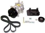
What you get in the kit, is the compressor, which takes gaseous refrigerant, and compresses it, and sends it off to the condenser. The Sel-Tec compressor they give you (so I’m told) is better than the old Sanden SD-7, which is what most of the dealer-installed kits have. They supply a bracket that bolts onto the stock a/c bracket as well as an idler pulley and a longer belt.
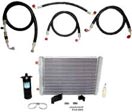
You also get the condenser, which is responsible for taking the compressed gaseous refrigerant, and bleeding off its heat. The condenser is basically a huge radiator that sits in front of your current radiator. They include all the bracketry to bolt it up very easily.
You also get the accumulator/dryer (the little black can thingy) which acts as a filter/moisture trapping element for the now-liquid refrigerant coming from the condenser. They supply you with 2oz. of lubricant which you put in the accumulator to act as a lubricating and filtering bath. You also get all the pressure hoses with proper fittings and correct lengths already made for you.
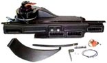
The most difficult piece of the kit to install is the evaporator/control unit. Inside the unit is another smaller radiator where the liquid refrigerant changes back into a gas, and part of physics is that a state change from liquid to gas gives a cooling effect, and that’s exactly how all A/C units work. The reason this part is so difficult to install is that you have to make room for the large fan motor and bulky unit itself under/behind the dashboard in the maze of wires and throttle and heater cabling. You are also required to drill a couple of holes in the firewall to feed the refrigerant lines through. I may opt to have this installed by a professional when I take it to get the system evacuated and charged.
Day One
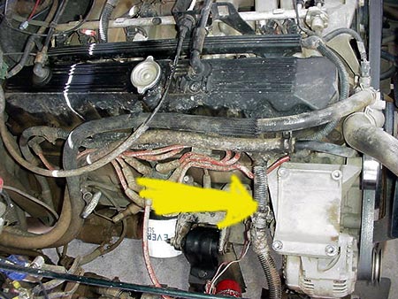
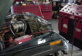
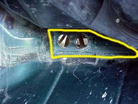
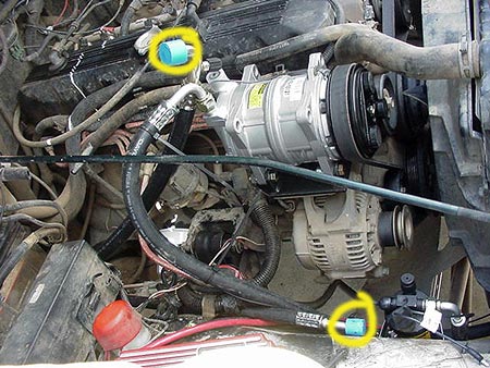
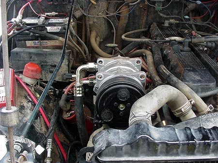
The first thing you will want to install is the compressor. The proper mounting location is the large flat area with 4 bolt holes if you haven’t already guessed.
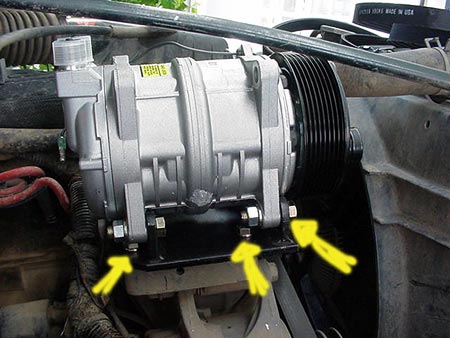
You will first bolt the bracket to the mount using the four 8mm bolts with lock washers, then you will bolt the compressor to the bracket using the supplied larger bolts, nuts, and lock washers.
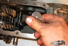
Then, to mount the idler pulley, you must remove the alternator so you can get to a nut to remove a bolt and install it. The alternator I believe uses 15mm sockets on the front, and the idler bolt is a 15mm bolt head and a smaller nut. I used a crescent wrench to hold the nut while I unbolted it.
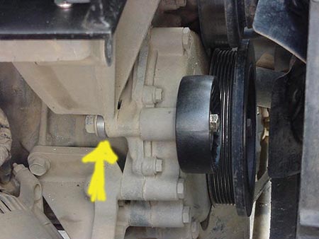
After you remove this bolt and nut, put the idler pulley on the new supplied bolt and bushing, and put the 1/4″ spacer on the end with the nut so the belt will ride properly.
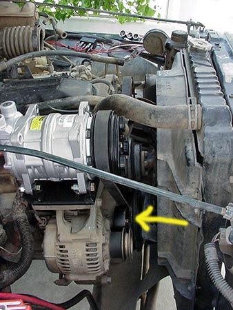
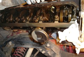
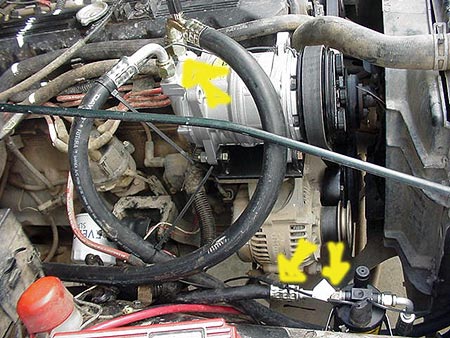
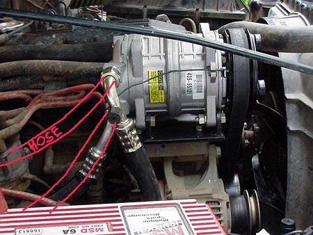
Rebolt the alternator on, then loosen the power steering pump to change the belt out. My power steering bolts were all 1/2″ or 14mm. In the picture here, you can see the correct routing of the new belt.
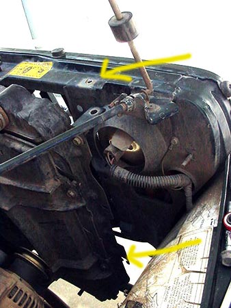
Next, we start on the condenser. Taking the brackets supplied, bolt them on, and attach the upper and lower hoses. There are two ways to mount the condenser, the hard way requires that the radiator to be drained and removed so that the ability to drill and screw in the top brackets is easier for those without a wide selection of tools. The easy way is to unbolt the radiator bracket with the two bolts on the cowl, and two lower radiator bolts.
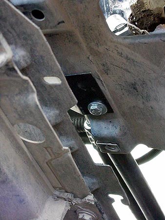
Once the radiator is unbolted, you can push it back far enough to drop the condenser down between the grill and the radiator. The condenser actually will come into the space between both, suspended between both vertical body mounts with the brackets. Two rubber well-nuts are slipped into pre-existing body holes, and are bolted snug.
There are 4 holes on the top brackets of the condenser that are drilled into the cowl, and self-tapping screws are used. You can unbolt the fan from the water pump, and unbolt the plastic fan shroud to push the radiator down far enough to get a clearance to drill for them.
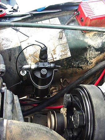
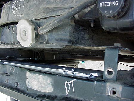
Bolt the radiator back into place, then run the high pressure lines back up under the radiator somewhat like the diagram included, and tighten one onto the compressor (making sure to use the proper size O-ring on the flanges), and the smaller, shorter, lower one onto the inlet side of the accumulator after you fill it with the supplied 2oz. of synthetic lubricant that is included. Attach the cable to the top of the pressure switch, and connect the long end to the clutch cable on the compressor.
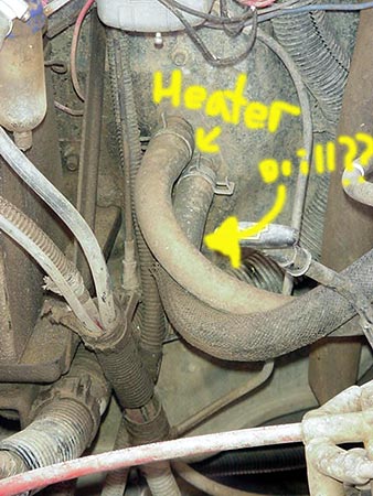
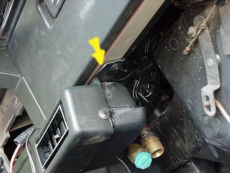
To install the evaporator, you are required to drill two holes in the firewall below the heater hoses, although some Jeeps will have pre-knocked out and plugged oval holes for the lines already. Mine however does not have them, and I am not sure yet whether I want to do it myself or let a seasoned pro start cutting.
Day Two
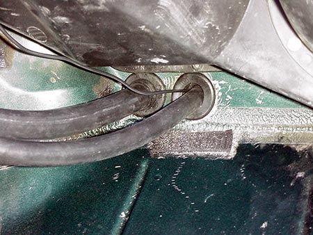
After calling AMA, and talking with Jack, their Jeep specialist, I felt confident enough to handle installing the evaporator/fan unit myself. Jack suggested a location to drill the holes for the lines to run. So I drilled two 1-1/4″ holes in the firewall just below the heater unit, There is a spot that is about 2″ tall and about 9″ wide that is big enough to run the lines on the passenger side.
I then ran the lines starting in the engine compartment and threading them into the cab.
The next item of business, Jack told me, was to screw the passenger side of the unit to the dashboard, lining it up with the glove box. An ex-post-facto suggestion i will make is to make sure that the metal strap is flush with the dashboard or even slightly recessed to allow clearance for the glove box hinge. This will put the hole for the self-tapping screw off-center, do not worry because the metal frame of the dashboard is very very strong.
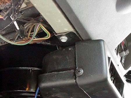
Then pilot drill and screw on the drivers side.
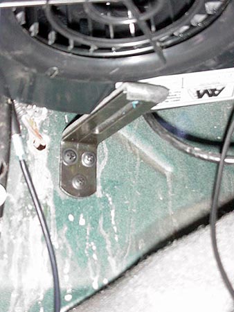
Then drill 3 holes in the firewall to attach the supporting bracket for the fan housing. You will want to lift the back of the unit as high as you can to get the right amount of clearance. after I installed this bracket, I had to trim about 3/4″ off of the top of the gas pedal lever to clear the fan housing.
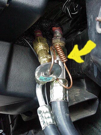
Attach the larger hose to the evaporator after feeding the rubber firewall grommets onto both lines. Next, install the pressure valve and smaller line. The pressure valve is a temperature activated unit that senses the temperature of the refrigerant leaving the evaporator, and adjusts the flow of refrigerant to prevent icing up. The copper coil will have to contact the exit fitting and is held in place with a supplied metal clip.
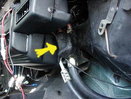
After you have it clipped on, use the supplied black insulating tape they supply (it’s got a weird name) around the valve and the fittings to insulate it from improper readings.
Feed the black clutch wire through one of the grommets into the engine compartment. Then lightly spray the grommets with a light lubricant like wd-40 and work them into the firewall.
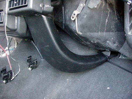
Then attach the hose cover to the housing with 2 self tapping screws and some zip ties on the lower end. Jack said to use 1 self tapping screw, but it didn’t reach. Zip-ties are fine IMHO.
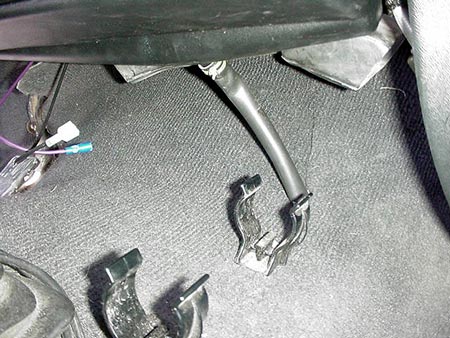
Drill a hole in the transmission tunnel 5/8″ in diameter for the evaporator drain hose to feed through. You can get it closer to the firewall if you drill it before you install the evaporator. Slit carpet accordingly.
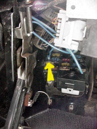
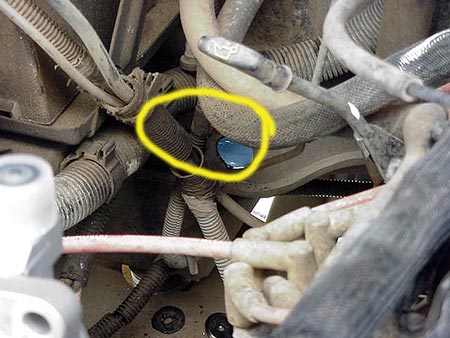
Attach ground wire to a good ground, then cut the rubber connector off of the blue power wire and crimp on the supplied spade terminal, and slip it into the fuse panel in the location that says “Cruise” or another similar open socket.
Connect the black clutch wire to the pressure switch at the accumulator, then attach the lines to the compressor and the accumulator.
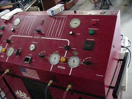
The system should be finished. Now take it to your local a/c servicing location and have them evacuate the system, (which also will tell you if you’ve got any minor leaks that need to be addressed from over tightening the fittings, or not pre-lubricating the o-rings before installing them.
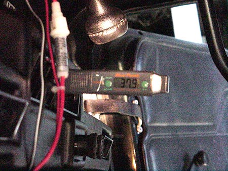
Vi-o-la!! a working air conditioning system in a Jeep! Check that out boys and girls – 37.9 Degrees Fahrenheit!!!!!
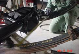
This system is so cold that it chilled my hand while working the stick-shift. All I need now is a vent-mounted cup holder and i’ll never have to worry about a frosty beverage again!
Some thoughts after installation
I would likely try to run the return line (the big fat one with the black fitting on it) slightly more to the back of the compressor than I did, simply because there is precious little clearance between it and the hood, and I’m sure it rubs slightly. Turning it about 120 degrees towards the back of the engine compartment would offer a little better clearance. Jeeps with a 1″ or more body lift and no motor mount lift should not have this clearance problem. The current configuration also does not allow for reinstallation of my York Compressor at this time.
UPDATE: Two guys on JU suggested a few ideas to solve both the York Bracket problem, and the hose rubbing the hood problem. The suggestion for the hood problem was to rotate the compressor 90 degrees counter clockwise in its mount to put the fittings on the side of the compressor. I contacted AMA about this, and they said that this would not affect the oiling of the compressor in any way. “As long as it’s not mounted upside down,” they said.
This solved the clearance issue, however I now have a hosing routing issue when I plan on reinstalling my Kirby Bracket for my york. I will have to de-pressurize the system, re-route the hoses properly, and then get the system evacuated and re-charged for about $80 in refrigerant and labor. :-( Oh well…. should have thought about that when i was installing the system. D’oh!…
Adapting the system so I can still use my Kilby OBA York bracket will come another day, so look for it. Basically, it involves trimming the AMA bracket a bit on both sides, and moving the 4 bracket mount holes to the passenger side a bit, maybe 1/2″ to clear the bracket, and then making a brace to attach the top of the Kilby Bracket to the ears on the compressor.
In Conclusion
Total Cost:
AMA Kit: $697.00
R-134a Evacuate and Recharge with 24oz of refrigerant: $79.00
Total overall: $776.00
Not bad for an aftermarket kit. If you do this job yourself… you easily save… oh… at least $400.00 in labor.