Jeep Articles & News
JB Conversions Lomax 4-to-1 Gearset
Jeep CJ-7 Project: JB Conversions LoMax 4 to 1 Gearset for the Dana 300
The Dana 300 transfer case is arguably the “best” factory transfer case that came on Jeep vehicles. Gear driven, 2.62:1 low range, and wide application possibilities make this the next best thing to an Atlas swap. Parts availability is better than the Dana 18 & 20 cases, especially when you look at improving the low range gearing. We opted for the JB Conversions LoMax 4:1 gearset when it was time to go through the 300 on our 1986 CJ-7. We decided while we were at it a clocking ring, twin stick shifter, and custom crossmember to gain some ground clearance would round out the modification nicely.
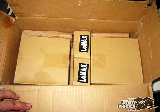 Nice package
 Rebuild kit
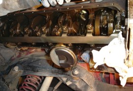
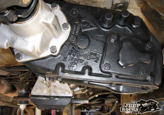 Dana 300 transfer case
The JB Conversions LoMax kit was very well packaged and contained complete installation instructions. We also purchased the master rebuild kit from JB Conversions which greatly simplified collecting the parts necessary to do the job. I recommend a factory service manual be used in conjunction with the supplied instructions to make sure you have complete torque specifications. We’ll try to cover everything here so you don’t have to go out and buy a factory manual.
We started by ensuring we had the tools and equipment necessary to complete the job. We used a set of tall jack stands, a hydraulic jack, 20 ton hydraulic press (*optional), good heavy duty snap ring pliers, 6″ and 8″ jaw pullers, smooth jaw vise, brass drifts, brass hammer, die grinder, impact wrench, and an assortment of basic hand tools. A transmission jack attachment is also mandatory if you are trying to do this yourself. A good time to check your tools is while reading the instructions from cover to cover. This will ensure you are not surprised when you discover you need a certain tool.
This job cannot be completed without a press. However, you can pay $60-$100 for some shop time at your local machine shop to do it without going out and purchasing an expensive press. We’ll elaborate on the sequence of assembly if you choose to have the bearings pressed on at a shop.
Step 1. Check the parts and your Jeep
Unpack everything and check the parts against the packing list. This will ensure that you do not tear your Jeep apart and find out that something will prevent you from completing the installation. The only part that I purchased that did not come with the JB Conversions master rebuild kit was the transmission rear output shaft seal. This is Napa seal #19211 for our 5 speed T-5 trans. I wanted to make sure the seal was good since we had everything apart anyway and were installing a new input shaft. Check your application to make sure you get the correct seal. Now is a good time to install a new trans mount if yours is worn out or if you are still running the stock mushy rubber…
Step 2. Read the Instructions Again!
Well, do it. You will be surprised at how much easier the job will be if you have an idea of what you are doing next at each step.
Step 3. Transfer Case Removal and Cleaning
With transmission jack and jack stand at the ready, gather the tools necessary to remove the crossmember and drop the transfer case and get under the Jeep!
Start by removing the front and rear driveshafts, the speedometer cable, and the transfer case shift boot and knob in the cab. Place a jackstand under the transmission as high as possible in a location far enough forward to allow the hydraulic jack to be centered under the crossmember. Remove the transmission mount and torque arm bolts. Begin loosening the crossmember bolts at the frame and make sure the jack is securely under the crossmember. Remove one crossmember bolt at a time and check the jack to make sure the crossmember is not going to shift as you pull the bolts. Once all bolts are removed, slowly lower the jack so the transmission rests on the jackstand. Remove the crossmember and set it aside. Check the jackstand and make sure the transmission is properly supported. With the crossmember out of the way, removing the shift lever is much easier. Remove the large nut holding the lever on the shaft and the cotter pins that secure the shift cam pins to the push rods. Remove the lever.
Place the transmission jack under the transfer case in preparation for removal. Loosen the transfer case to adapter bolts and nuts. Slide the jack/transfer case back to disengage the input shaft. The transfer case should be free.
Cleaning is fun. I wish I had a pressure washer. I accomplished the cleaning of 18 years of caked on, baked on grease and dirt with many cans of Gunk Engine Brite and a stiff wire brush. This took over an hour of spraying, soaking, and brushing… After cleaning, I drained the fluid and tilted the case up to drip in a pan overnight to get it as empty as possible (I have to sleep sometimes too).
Step 4: Transfer Case Disassembly
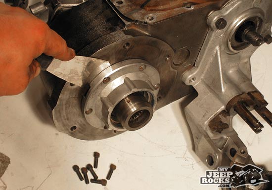
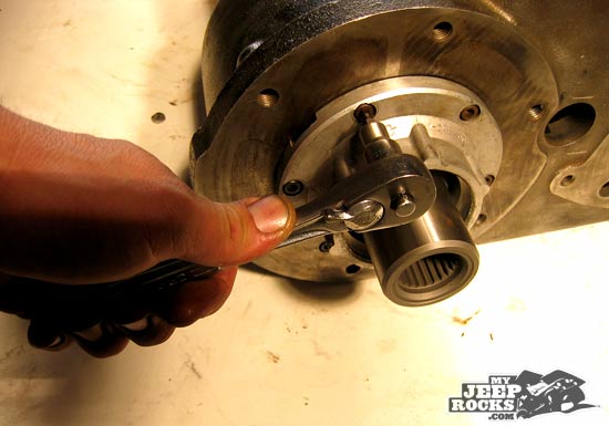
Remove the bottom cover and front and rear output yokes.
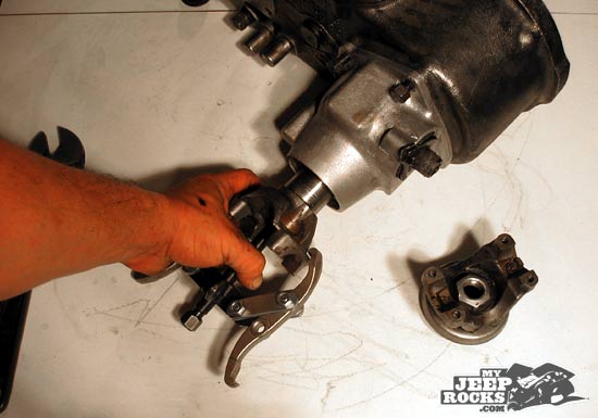
Carefully work the bottom cover off with a putty knife or thin screwdriver making sure you don’t pry too hard and bend the lip. You will need a 1 1/8″ socket and either an impact wrench or a yoke holding tool to remove the yokes. The smaller puller may also come in handy.
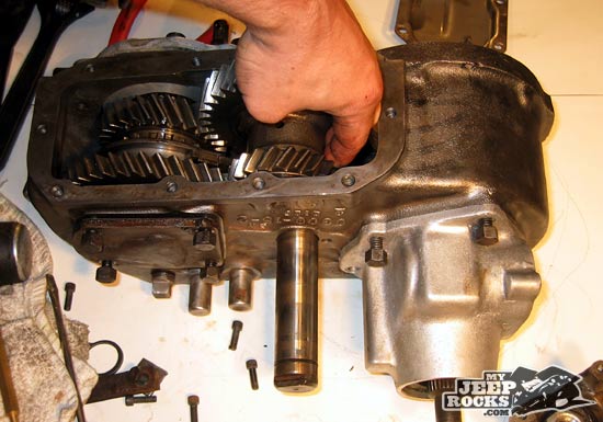
Remove the cross shaft retainer bolt and tap the cross shaft out with a brass drift. If you are not doing a complete rebuild, make sure you keep track of the bearing rollers and 3 spacers as you remove the gear. Remove the intermediate (idler) gear and set aside.
Remove the shift fork set screws with a 3/16″ allen socket.
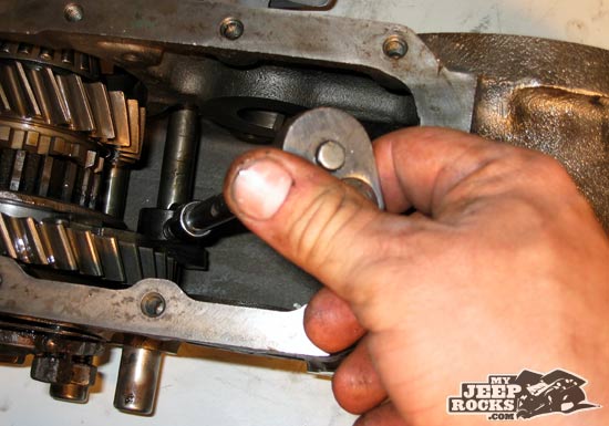
Using a punch through the hole in the end of the shift rod, remove each shift rod by rotating and working them out of the housing.
Flip the case over so the shift rods are accessible. Remove the bolt for the shift fork seal retainer. Remove the pressed detent plugs and switch from the front bearing retainer housing. Ours did not have a threaded plug as the JB Conversions instructions suggest, they were all pressed in plugs. We threaded two of the holes with a 1/8″ NPT pipe tap to install the plugs supplied with the JB Conversions kit.
Flip the case back over and remove the shift forks starting with the smaller fork.
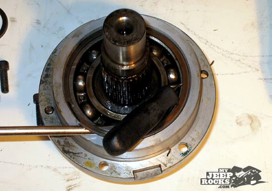
Remove the 6 allen screws holding the input bearing retainer to the housing. Remove the input bearing and gear assembly from the housing by tapping with a rubber mallet and gently prying between the housing and input assembly.
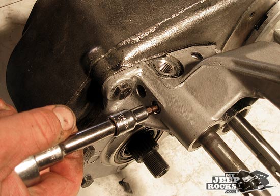
Remove the speedometer drive gear from the rear output housing by removing the retainer bolt and rotating the speedo gear to work it out. Use a puller to remove the rear output housing. Keep the shims behind the bearing.
Remove the rear bearing retainer plate and rear bearing outer race from the case.
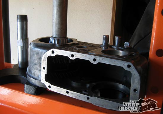
Remove the front output bearing retainer using a rubber mallet and gently prying to work the housing loose.
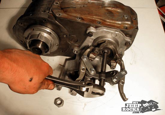
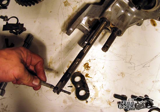
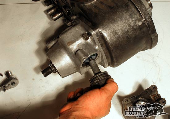
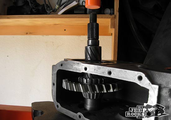
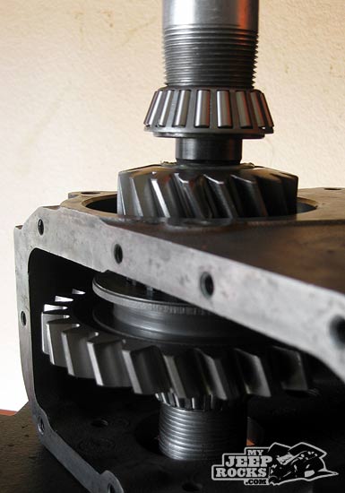
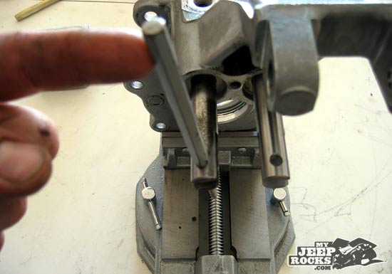
To illustrate the methods you can use if you do not have a press, I removed the front output shaft rear bearing by pressing the end of the shaft with a puller placed inside the housing as shown here. You can then remove the front output front bearing and gear outside of the case, shown in the next step. You can also use the press if you are so equipped. Remove the clutch gear slider from the shaft.
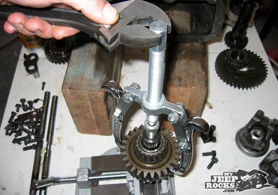
Remove the front output shaft front bearing with a gear puller to separate the gear and bearing from the shaft. The JB Conversions instructions illustrate this same step using a puller with the shaft still in the case. You can also use a press if so equipped.

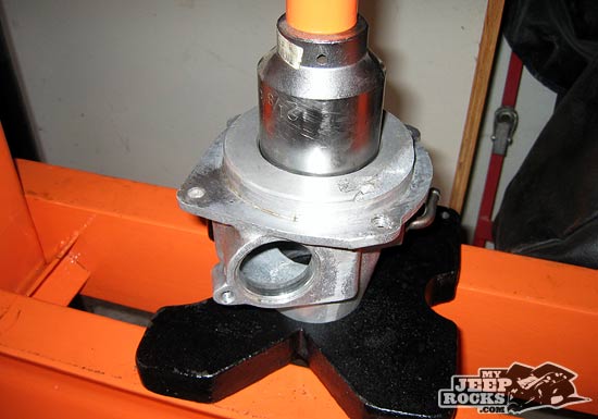
Reposition the case in the press and remove the rear output shaft rear bearing and gear from the shaft. If you do not have a press, you will need to take the case to the machine shop at this point and remove the rear output shaft bearings/gears.
This should take two press operations which cost about $10 a piece at a shop near me. This is also a good time to take your new input shaft and bearing to be pressed together if you are doing a rotation kit. You will need the complete input shaft/bearing/housing/gear assembly and your snap ring pliers, shims, and feeler gauge with you at the shop to set the input shaft endplay. See the last step in this section for details on the input shaft endplay. You also can do this once you are ready to install the new gears in the case so you can take everything to the machine shop at one time.
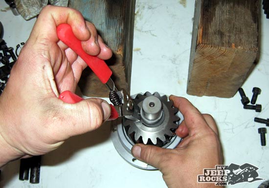
Measure the input gear to retaining ring clearance using a feeler gauge as shown in the JB Conversions instructions (I botched this pic somehow, but the JB instructions are very clear on this measurement). Note the measurement. The gap should be 0.00″-0.003″. Disassemble the input gear by removing the retaining ring with snap ring pliers, shown here.
Remove the input gear from the shaft by placing in the press, if necessary (ours came off without the press). If you are installing the rotation plate kit with the longer input shaft, remove the retaining ring from the groove in the aluminum housing (shown at left) to remove the input shaft bearing from the housing. You will not need to press the original bearing off the shaft unless you want to measure the original shim thickness to get the gap close the first try. Our original input bearing did not have shims behind it and the gap between the snap ring and gear was very large (about 0.012″). I suspect this was part of the transfer case slop we were experiencing. If you are not installing the rotation plate kit, follow the JB Conversions instructions for the input shaft.
Install new shims on the input shaft and press the new bearing on the shaft. Reinstall the bearing into the housing and install the retaining ring and input gear. Install the snap ring. Measure the snap ring gap and verify 0.00″-0.003″. If the gap is incorrect, remove or add shims as necessary. I set mine at 0.0015″.

This step only applies if you are doing a complete rebuild and have a new roller bearing for the rear output shaft/input shaft mating bore. Look at the bearing and note approximately the depth in the shaft. Using a slide hammer and appropriate puller attachment, remove the internal roller bearing from the rear output shaft. Install the new bearing with the appropriate driver, making sure to check the depth of the bearing as you go. Drive the bearing in to about the same position it was in before. Mine was almost bottomed out, but not quite. If you’re not sure, insert the input shaft into the end and see if it goes all the way in. If it does, you have the bearing in far enough.
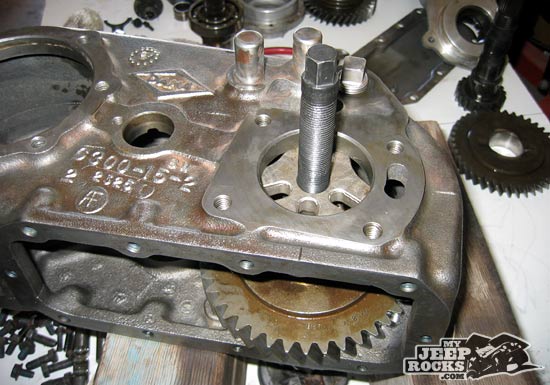
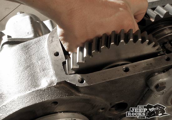
Step 5: Grinding the Case for Intermediate Gear Clearance
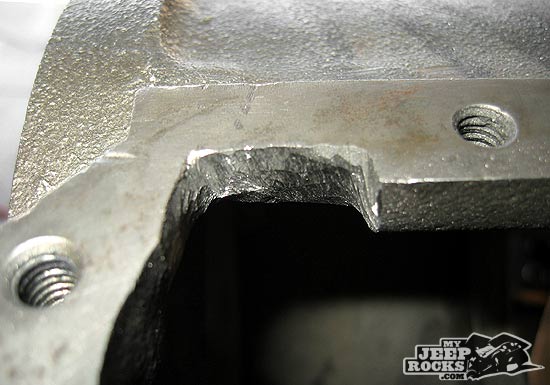
This step requires the careful use of a die grinder to make clearance for the new larger intermediate gear during installation. I used a combination of cutoff wheels and grinding wheels to get the shape shown at left. This is necessary because the new larger diameter intermediate gear will not fit between the front shaft gears and the case, which will become very obvious once you start assembling the new gears.
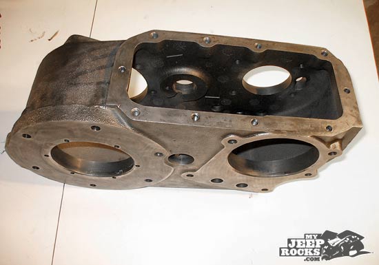
After grinding the recess, you must wash the case very thoroughly with soap and water. I used an air conditioning condenser brush to scrub every opening and recess in the case to ensure all metal and contaminants were removed. This is what the case looked like cleaned, stripped, and ready for assembly. I chose to paint the case after assembly, although you could paint it at this point if you wanted to spend some time masking the mating surfaces and making sure you don’t paint the threads or other critical areas. Otherwise, if you want to leave the input and output housings bare aluminum, you can mask them off after assembly. Or you can simply spray the whole mess if you don’t care about shiny aluminum…
Step 6: Preassembly Checks on New Gears
This step is critical to ensure no interference between the new gears and the original shafts. The main reason these checks are necessary is because the old shafts could be worn at the shoulder mating surfaces with the gears which could cause the new gear to bind once everything is put back together. The instructions are very explicit on what to check. Here are some full color pics.
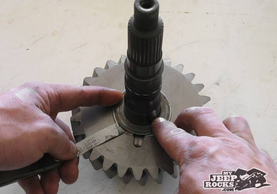
Checking the rear output shaft gear clearance. Place the 27 tooth gear and thrust washer on the shaft and check for clearance between the washer and gear face. Ours came out to about 0.004″ clearance.
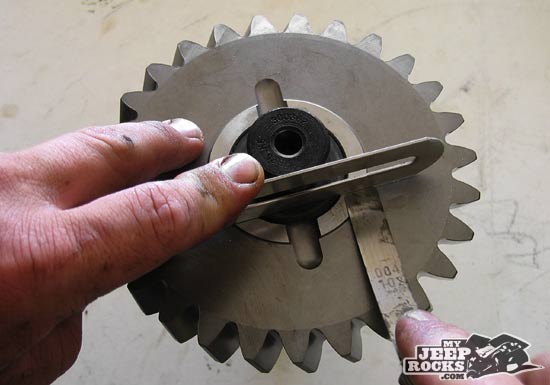
Checking the front output shaft 27 tooth gear clearance. Place the gear on the shaft. Using a straight edge placed across the shoulder on the shaft, check for clearance between the straight edge and gear face. Ours came out to about 0.004″ clearance here also.

Checking the front output shaft 18 tooth gear clearance. Using a straight edge placed across the shoulder on the shaft, check for clearance between the straight edge and gear face. Ours came out to about 0.004″ clearance here as well.
Step 7: Transfer Case Assembly
The procedures to install the new gears and assemble the transfer case are basically the same as disassembly in the reverse order. The following pictures and tips should help you through the instructions and/or service manual. The first 4 instructions of this section should be completed at a machine shop if you do not have a press (along with the input shaft assembly noted above). You will probably need to actually watch/help the machine shop assemble to make sure it is correct, unless you walk in there with a service manual or the JB Conversions instructions. We illustrate the assembly procedures in a slightly different order than the instructions so that you have the steps requiring a press in order if taking everything to a machine shop for assembly.
The rear output shaft assembly is completed by installing one of the two 27 tooth LoMax gears on the rear output shaft with the dogs on the side of the gear toward the dogs on the shaft. Install the thrust washer between the gear and the bearing. Press the bearing (#25880) onto the shaft until it contacts the washer. The gear should spin on the shaft when you’re done.
The rear output shaft assembly is completed by installing one of the two 27 tooth LoMax gears on the rear output shaft with the dogs on the side of the gear toward the dogs on the shaft. Install the thrust washer between the gear and the bearing. Press the bearing (#25880) onto the shaft until it contacts the washer. The gear should spin on the shaft when you’re done.
Place the slider ring and 18 tooth LoMax gear on the shaft with the dogs on the gear toward the dogs on the shaft. Using a suitable tool underneath the bottom bearing to prevent damage to the cage, press the bearing (#86649) onto the shaft until it contacts the shoulder on the shaft. Verify the gear spins on the shaft when you’re done. This is the last assembly step which requires the use of the press (assuming you took the input shaft assembly with you to the machine shop as suggested above).
Remove and install the new rear output housing bearing cup. I used the press, but this could also be done by placing the aluminum housing in the oven at 200°F and the bearing race in the freezer for a half hour or so or until it’s good and cold. This usually works like a charm and the race will drop right in. Do the same for the front (shift rail) housing. I had to use a brass drift to get the bearing race out of the front housing, it was a bit stubborn and could not be easily pressed out because of the lip against the back side of the bearing race. I also used the press to install the new front race, but I believe if I had used the freezer/oven trick here it would have worked also. Worst case you can tap them home if they don’t drop all the way in.
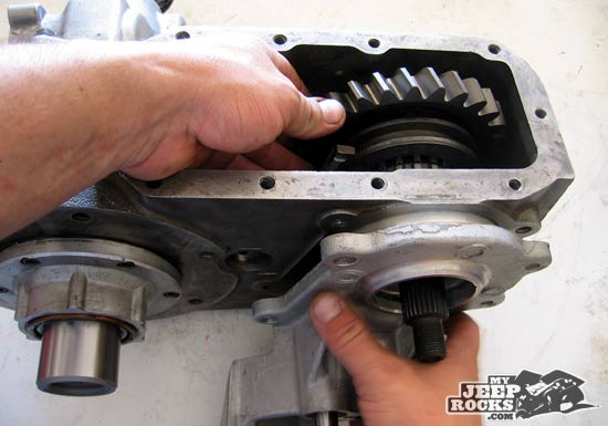
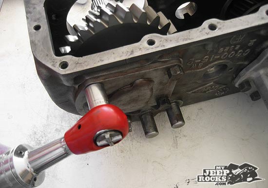
Place the sliding ring for the rear output shaft onto the shaft. Put a thin coat of RTV on the mating surface of the input gear assembly. Install the input gear cluster into the front of the case and align the holes using two of the capscrews. Tap the assembly into the housing, install the remaining allen screws, and torque to 10 ft-lbs (14 N-m).
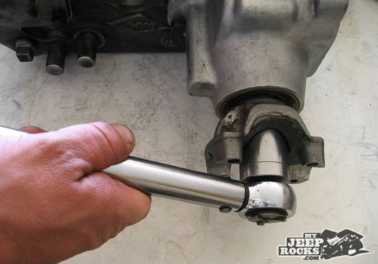
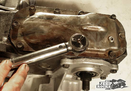
Install the new seal in the rear bearing housing. Install the rear bearing housing. Torque the housing bolts to 35 ft-lbs (47 N-m). Install the rear output shaft yoke. Tighten the locknut with 100 ft-lbs (136 N-m). It may be helpful to have someone else hold the case down while you torque the nut. Check the rear output endplay using a dial indicator on the end of the shaft. Ours came out right on with new bearings and the original shims… lucky me.
Place the front output shaft rear bearing cup (#M86610) into the rear of the case. Install the retainer plate and shims in place behind the bearing cup. Do not seal yet in case the endplay is not correct. Tighten the bolts to 35 ft-lbs (47 N-m).
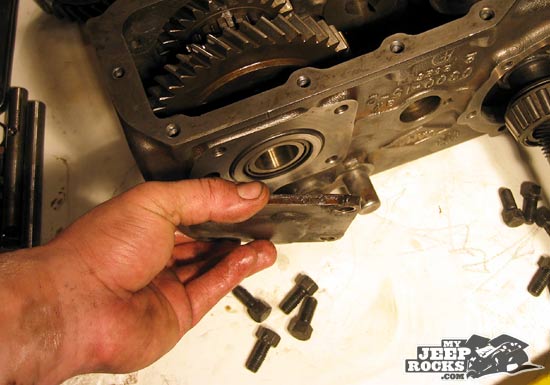
Install the shift forks into the case, starting with the large fork. Line the forks up with the shift rail bores in the case.
We threaded two of the interlock plug holes with a 1/8″ NPT pipe tap to install the plugs supplied with the JB Conversions kit.
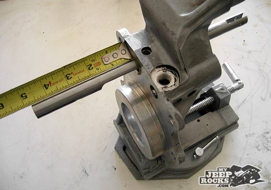
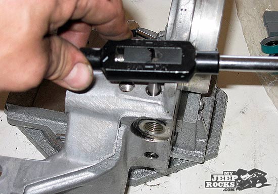
This step picks up with step #19 in the JB Conversions instructions for assembling the shift forks. Place the springs into each of the shift housing holes. Place the detent ball into the left hole on top of the spring. I used some grease to help hold the ball in place. Insert the proper shift rail (the new one provided in the kit in this case) into the shaft rail bore up to the detent ball. Position the rail with the slot facing vertical and the detent cutouts on the rail facing toward the other shift rail bore (toward the center of the housing). Press the detent ball down with a round punch while pushing the rail into the housing. Push the rail forward until 4 11/16″ of the rail remains exposed. Do not rotate the rail.
Insert the pill shaped interlocks into the horizontal bores in the side of the housing. They should seat up against the cutouts of the first shift rail. You should not see the interlocks when looking through the second shift rail bore. If you do, the first shift rail is not positioned correctly and the cutouts on the rail are not allowing the interlocks to go all the way in.
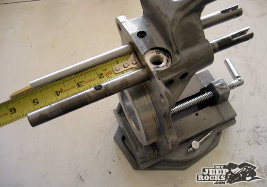
Position the second shift rail and detent ball similar to the first rail. Be sure the detent cutouts on the shift rail are facing the interlocks (the center of the housing) with the slot vertical. Press the detent ball down and insert the rail until 5 5/16″ of the rail is exposed. Do not rotate the rail. Be careful when handling the rails, especially the brand new one, because the machined edges are very, very sharp. I found this out the hard way and it drew first blood…
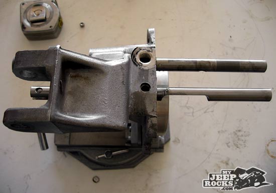
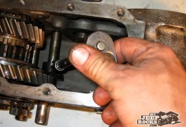
This is how it should look after rotating the rails into position.
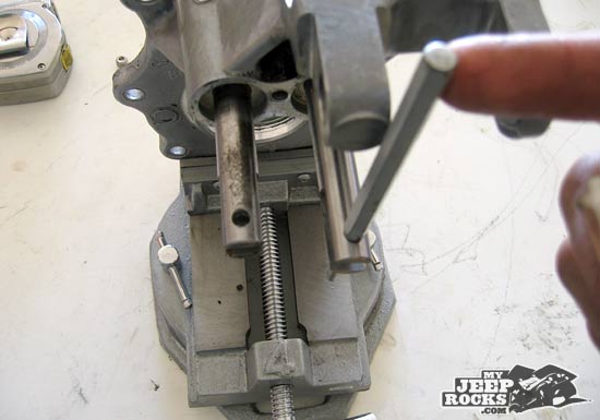
Rotate the second rail counter clockwise (when looking at them the same way you were when installing) 90°. The detent ball should pop into the detent groove in the shaft. My finger is showing the direction to rotate the rail in this pic.
Rotate the first rail 90° clockwise. Tap the rail back out (from the way it was installed) to pop the detent ball into place. Tap the first rail back one more notch until the ends of the rails are even. This is neutral. Leave them in this position.
Install the plugs and switch in the shift rail housing. I used some PTFE pipe thread sealer on the plugs.
Insert the aluminum housing/shift rails into the case. Put some oil on the shift rails to help them slide through the shift forks. This is a bit tricky and you may wish you had a third hand for this step. Once you get the rails all but about 1″ in, put a thin coat of RTV on the aluminum housing. Insert the shift rails the rest of the way by lining up the rails with the holes in the opposite side of the case. Install the housing bolts and torque to 35 ft-lbs (47 N-m).
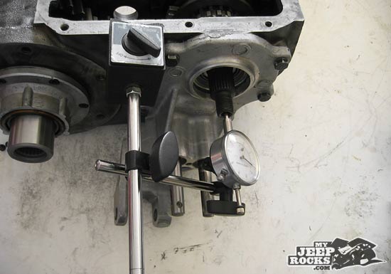
Check the front output shaft endplay using a dial indicator. Seat the rear bearing against the cover plate by tapping the end of the front output shaft with a rubber or plastic mallet. Position and mount the dial indicator on the end of the output shaft and zero the indicator. Pry the shaft back and forth. The end play should be 0.003″ – 0.006″. If the end play is incorrect, add or remove shims and recheck. Make sure to reseat the bearing before rechecking. Once endplay is correct, install the rear bearing shim pack and cover plate with a thin coat of RTV and torque the bolts. You must use a VERY thin coat of RTV on each shim face to ensure a proper seal. Recheck endplay after torquing cover bolts in place to verify the RTV did not affect endplay. Install the front output seal, yoke, and nut. Torque to 100 ft-lb (136 N-m). Again, a helper is useful to hold the case down while torquing the nut.
Install the shift fork setscrews using medium Loc-Tite and torque to 14 ft-lbs (19 N-m).
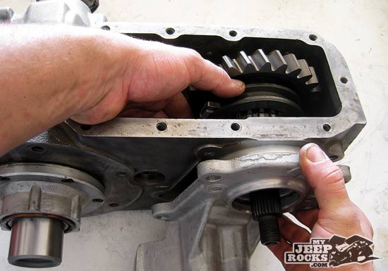
Install the needle bearings and steel spacer rings into the idler gear. Use thick grease to hold the needle bearings in place. Place one of the thrust washers into the case using thick grease to hold it in place. Use the cross shaft to hold the washer in place by inserting it just enough to support it. Install the second thrust washer (again, grease) on the opposite side of the case. This is why you ground the recess in the case…
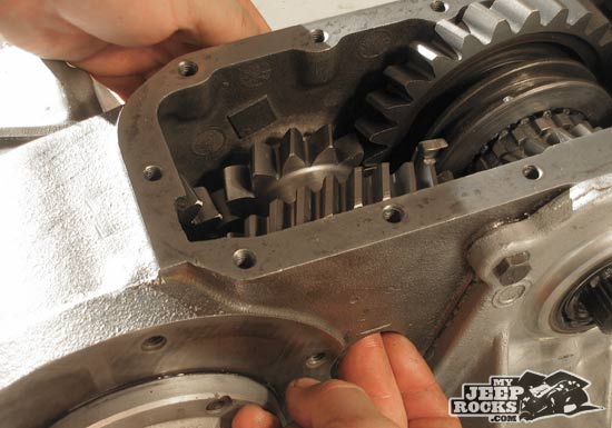
While holding the second thrust washer in place with your finger, lower the idler gear in place by rolling it as you lower it. When the idler gear is in place, insert the cross shaft through the gear. Make sure the needle bearings stay in place as you insert the shaft. Pay attention to the orientation of the cross shaft so the flat spot is oriented correctly for the retainer plate once it is all the way in. Tap the cross shaft in with a rubber hammer and install the retainer plate and bolt. Torque the retainer bolt to 23 ft-lbs (31 N-m).
Install the inspection cover with a thin coat of RTV on the gasket. Torque the cover bolts to 15 ft-lbs (20 N-m).
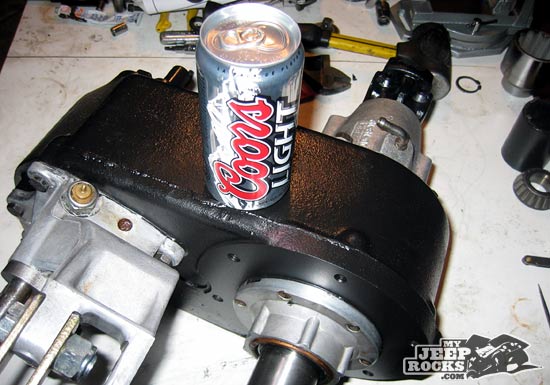
Woooo-hooooo! 4 to 1!
Step 8: Installing the Transfer Case and Custom Crossmember
We’re not going to detail the installation of the transfer case – if you made it this far, you should be able to get it back in there!
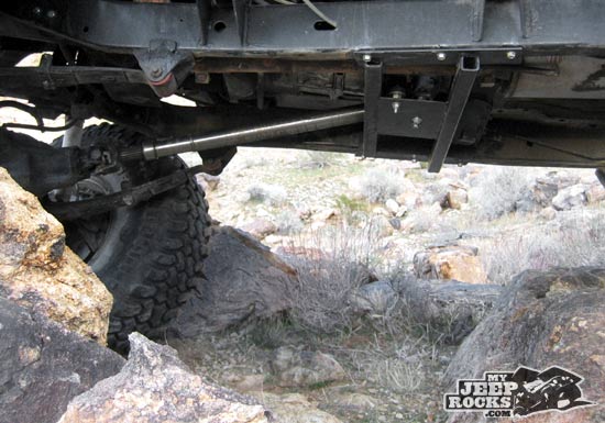
The crossmember ended up 1 1/2″ below the frame all the way across, with the square tubing directly under the transfer case. I took this approach as opposed to moving the rear tubing further rearward so that I don’t necessarily have to run a heavy skid plate to protect the transfer case. I could have extended the angle iron further back on the frame and mounted the rear cross tubing inside the frame rails. This also would have made the trans mount plate much longer, which would likely need stiffening in order to make strong enough.
As it is now, I used 3/16″ plate and it seems to be plenty strong. In spite of the 1 1/2″ drop from the frame, this is substantially more clearance than the factory ~5″ drop under the transfer case.
The rotation plate was set up at the second hole up from stock, a bit of a disappointment considering I was hoping to make it totally flat. This was the best option considering substantial bashing of the passenger side floor is required to get it any higher (I did a fair amount of “clearancing” with my 5 lb friend as it is). We were able to clock the transfer case at the angle we wanted only after adding an additional inch to our 1″ body lift for a total of 2″. This also required adding some lift to the engine mounts so the driveline angles were acceptable. I accomplished this by welding some 3 1/2″ wide by 1 1/2″ tall C channel onto the existing motor mount frame supports. This was a bit tricky, but considering there are not any readily available engine lifts for CJ’s it was our only option (we have yet to find someone making these off the shelf).
We ordered up a twin stick shifter and shift boot from Rob at Quadratec. The twin stick shifter barely cleared the floor pan in the position we selected. I also had to heat and bend the shift rods about 10 degrees to get them to clear the center console.
As a result of the additional 3/4″ thickness of the rotation plate and the significantly higher position of the front output yoke, the front driveshaft was way too short. We took care of this by giving Tom Woods a call and ordering up a beefy 10″ slip front driveshaft. (See our writeup on the driveshaft here.) We opted for the polished clearcoat version which really looks great (it’s the only shiny thing in the pic above). It ended up at 34.5″ running length for our current setup. The shaft has about 4″ of compression travel at rest now which should still work for the front Dana 44 swap coming soon…
Sources
JB Conversions
P.O. Box 2683
Sulphur, LA 70664
(337) 625-2379
Tom Woods Custom Driveshafts
2147 N. Rulon White Blvd
Building 1, Ste 103
Ogden, UT 84404
(877) 4X-SHAFT
Quadratec
Rob, Extension 337
(800) 735-5337