 Tweet
Tweet
I remember seeing a pitman that had an angled hole for the TRE for this type angle on the drag link which is common with 3 link/Panhard suspension. I will see if i can find it again. The only other thing I would worry about with this setup is bump steer. With a drop arm you could lessen it, as long as you have space for it.
-
-
yea, there's room for a drop arm. I actually purchased one to begin with a while back, but I didn't realize that the ford Ranger's had different sized output shafts on the manual, and power steering boxes. The one I purchased was for power steering. The drop is good, but it's slightly to large around to go on to the manual steering box output shaft.
I wonder if shafts from other vehicles will fit? How do you go about measuring a tapered shaft like this, what's the common way to measure these things, just the smallest diameter of splines?[COLOR="#FF0000"]R[/COLOR]edneck [COLOR="#FF0000"]D[/COLOR]riveway [COLOR="#FF0000"]F[/COLOR]ab
www.DanielBuck.net - www.DNSFAIL.com - www.FurnitureByBuck.comComment
-
I am not sure on that, I have always had a regular Saginaw box. Maybe spline count?Comment
-
As is it will have bump steer. Figure out what saginaw box it is and what all it was used on and then you can find some pitman arms
This old stuff gets interestingComment
-
Apparently I picked one of the oddball steering boxes that wasn't used very often. I know for sure it was used on ford rangers (from like 84 to 96 or whatever), but apparently the MANUAL steering was not common.
I've got everything else figured out to fit this steering box, so I kind of don't want to ditch it for something else. Worst case I guess I could have one custom machined... but that sounds expensive, haha![COLOR="#FF0000"]R[/COLOR]edneck [COLOR="#FF0000"]D[/COLOR]riveway [COLOR="#FF0000"]F[/COLOR]ab
www.DanielBuck.net - www.DNSFAIL.com - www.FurnitureByBuck.comComment
-
Cut the splined piece off and make something along the lines of a genright pitman arm. Your welds are decent enough to do soComment
-
Oh yeah, the genright pitman is the one I was thinking of. You could build that.Comment
-
Hah, well it might be worth a try, I've got this flat pitman arm that I can't use, Might as well try, eh?[COLOR="#FF0000"]R[/COLOR]edneck [COLOR="#FF0000"]D[/COLOR]riveway [COLOR="#FF0000"]F[/COLOR]ab
www.DanielBuck.net - www.DNSFAIL.com - www.FurnitureByBuck.comComment
-
You have to, there is no choice!
Just don't start reading on the internet about modifying pitmans or you will learn that it is impossible and you will die if you try.Comment
-
Haha, I've already read thatOriginally posted by jonah View Post
I'll mock something up in CAD and see what I can come up with.[COLOR="#FF0000"]R[/COLOR]edneck [COLOR="#FF0000"]D[/COLOR]riveway [COLOR="#FF0000"]F[/COLOR]ab
www.DanielBuck.net - www.DNSFAIL.com - www.FurnitureByBuck.comComment
-
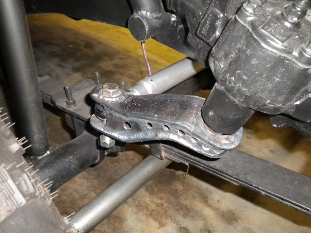
Anyway try to get the draglink close to horizontalComment
-
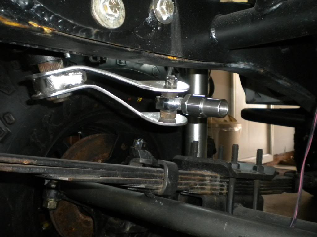
I want it as close to horizontal as I can, at ride height, correct? It's not going to sit a LOT lower when the motor and transmission is in there, but I'm sure 700 pounds will lower it an inch or so. I'll try and dig up a photo that shows the relationship of the frame to the tires, and try to guess at how much lower it will sit.
The angle wasn't very horizontal before with the old steering, actually I think it was worse, because the bell crank was in the middle of the cross member, not off to the driver side like the steering is now. I guess I never noticed any bump steer, all the "character" of the jeep must have masked that so I didn't notice it. HAHLast edited by daniel_buck; 01-24-15, 11:35 PM.[COLOR="#FF0000"]R[/COLOR]edneck [COLOR="#FF0000"]D[/COLOR]riveway [COLOR="#FF0000"]F[/COLOR]ab
www.DanielBuck.net - www.DNSFAIL.com - www.FurnitureByBuck.comComment
-
I think with the old bell crank style when the axle came up it would push both wheels out a little, so they probably counter acted one another. Plus if it had the normal bell crank slop, yeah, lots of "character" to say the least. lol
On this style when the axle comes up both wheels turn right, hence bump steer. Anyway, like Art said - as close to horizontal (at rest) as possible.Comment
-
Jonah, my jeep had already been converted to a single tierod setup, I'm actually only replacing the drag link, I'm not changing the tierod. So I think it should act the same? I know originally, they had two rods that came from the bell crank, one to each side, kinda like A arms on an independent suspension. Previous owner replaced that with the single tirerod setup that I have now.
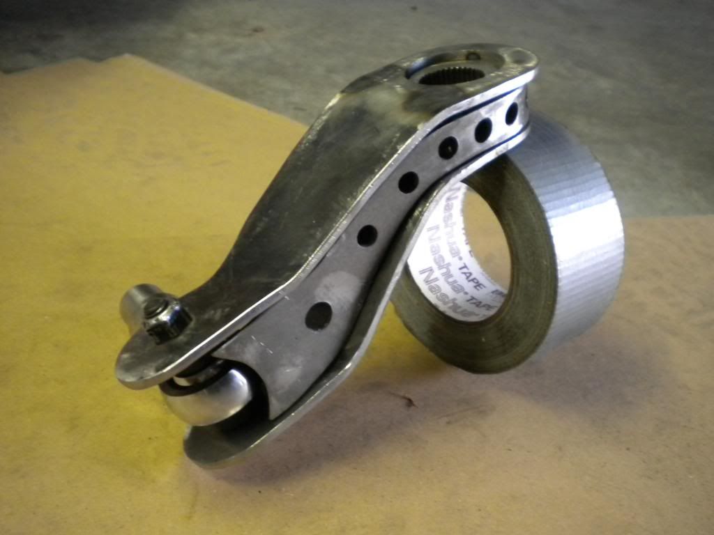
Something like this seems doable. I don't know if I'd put the speed holes in it though, I'm sure those would fill up with spiders haha
Not sure how thick this metal is in these photos, it LOOKs like 3/16". I know I could easily bend small pieces like this in my press, I've got some 1/4" and 3/8" plates that are probably about the right size.
 Last edited by daniel_buck; 01-25-15, 12:06 AM.[COLOR="#FF0000"]R[/COLOR]edneck [COLOR="#FF0000"]D[/COLOR]riveway [COLOR="#FF0000"]F[/COLOR]ab
www.DanielBuck.net - www.DNSFAIL.com - www.FurnitureByBuck.comComment
-
I see, yeah if you had the drag link/tie rod set up like that before, it would be about the same. Although if you had a lot of slop (as those often did) it may have soaked up some of the bump steer. I would just hate to have you miss the apex of a corner if it was a little bumpy. Could hurt your lap times, lol.
That looks like 3/16". I don't like those speed holes either, but yeah something like that. The genright is made from 1/4" which would be nice:
http://www.genright.com/ProductInfo....2#.VMR5GWR4pAcComment
Comment