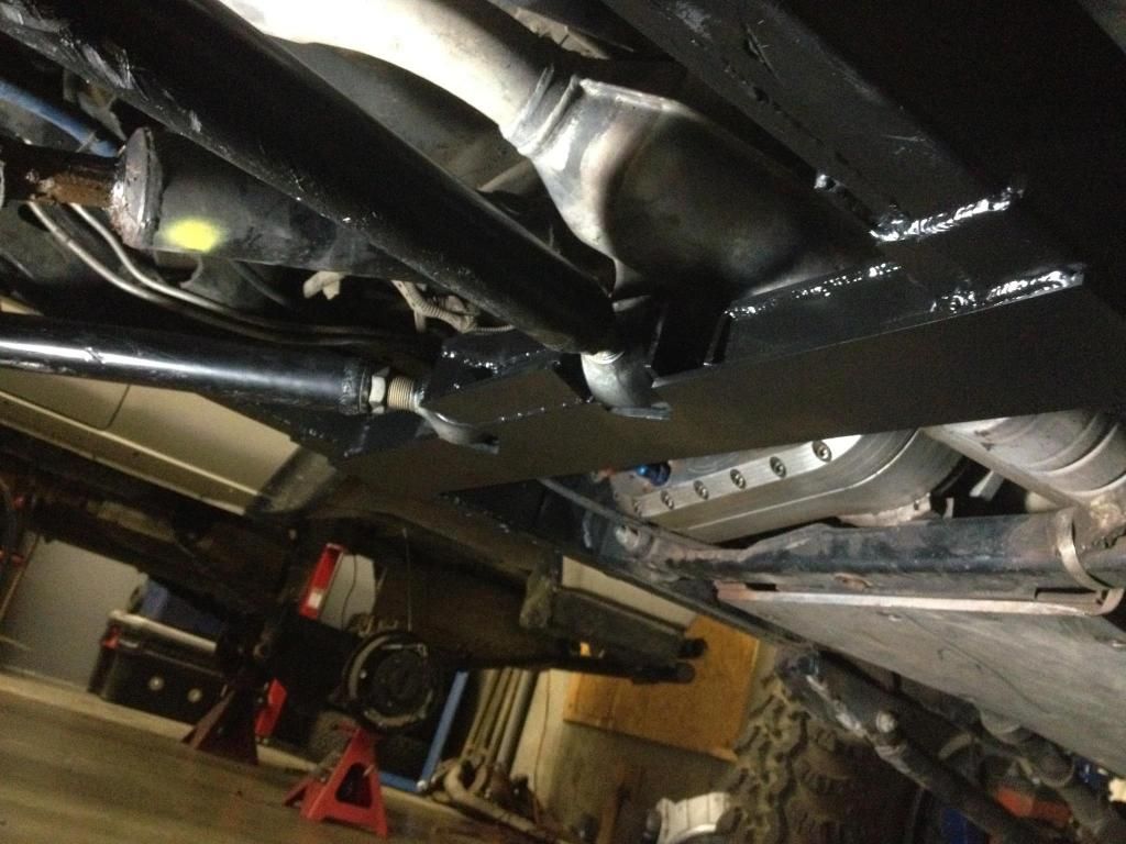
Still more to do to the rear suspension, but I had to prioritize my argon and I really want to get rid of those Teraflex arms up front. On to the front 3-link.
I've already dropped some hints, but my 3-link is going to be a little different than your typical TJ's. I'd looked forward to following convention and doing things fairly simply. Just some typical LCA brackets on the frame rails. Some extra holes in the UCA brackets. The more I thought about it, though, the more I wanted to take the roll-oversteer out of the front suspension, and that meant moving the frame-side LCA mounts inboard. What I needed to do that was a front crossmember. With that big ol' 4500 under there, there's only one place to put a crossmember without it doubling as the transmission mount, and that's right in front of the transmission, and under the neck of the bellhousing. So the crossmember had to be bolt-in.
It's a tight affair, but there's room. Gonna have to re-route that exhaust, though. Wouldn't you know it, though, there's a dog-leg in the frame right where my bolt-in crossmember needed to go.

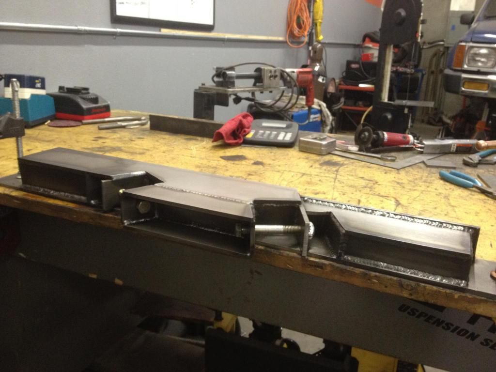
Well, I got to designing, and calculating and reckoning. Force will be coming from the front and from below. First thing I decided was that the bolts should go fore-to-aft (or aft-to-fore) so they wouldn't be in sheer. The crossmember would go in from the bottom. The bracketry would hold the crossmember in place securely front, back, and top. The basic crossmember would be a piece of 2�, .250� wall square tubing. Would have preferred completely fabricated out of 1/4� or better plate, but I didn't have what enough, let alone what I wanted, so I'd just have to reinforce the 2x2.
From there I played with a number of variations of design, both in my head and on the computer. Two bolts, three bolts, five bolts (adjustable height), different dimensions. Again, my entire design was built around the materials I had on-hand that I could spare for it. I also designed for the future when I may build a replacement crossmember or two.
Here are a couple of drawings of the bracketry that are pretty close to what I've made in steel.
First the the top view. This is pretty accurate, except that this shows the 2x2 crossmember with two 1/4� laminates for a total thickness at the brackets of 2-1/2� . If and when I make another crossmember entirely out of steel plate, I want it to be 3� thick front to back, so I modified the design for two additional 1/4� laminates to take up the space. None of my drawings reflect that, however.

Now the front view. The two main bolts are 5/8�. Lower bolts are (to the bottom of the frame) are 3/8�. Drawing is to scale. The location of the exhaust and the shape of the adjacent radius are subject to change.

By now some of you may be thinking �That's great for the exhaust, but what about the your ever-loving driveshaft?� To which I say, this is a redneck rig, it has no front driveshaft, silly! Just kidding. The driveshaft will be a two-piece affair. Here's a diagram. I paid a professional to do this.


 At least you're not trolling on the internet.

Leave a comment: